


 20 / 78

A D V A N C E D M A T E R I A L S & P R O C E S S E S | J A N U A R Y 2 0 1 6
2 0
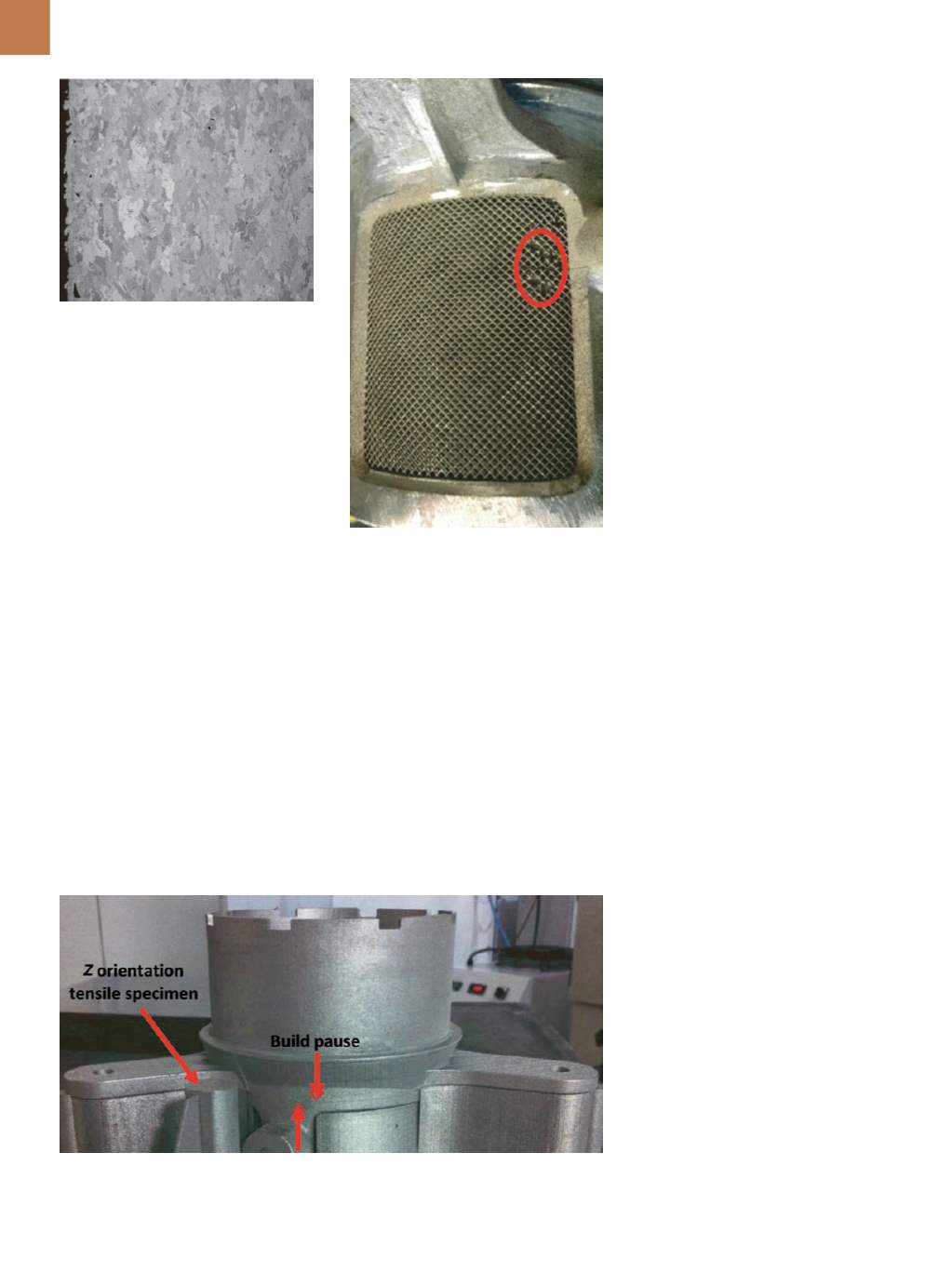
Fig. 4 —
Typical microstructure of a HIP’d
specimen. Courtesy of NASA.
Fig. 5 —
Defects in the integral mesh of a
development part.
Fig. 6 —
As-manufactured part with build pause visible.
Microhardness testing was per-
formed on one fully processed speci-
men. The specimen ranged from 432
to 466 HV
200
(44-47 HRC). Weld devel-
opment showed no defects at 20
×
magnification.
DEVELOPMENT CHALLENGES
A few challenges occurred during
development. Initial parts had dimen-
sional errors while the AM process was
being refined. For example, defects in
the integral mesh are shown in Fig. 5.
One part was scrapped due to
unconsolidated material in one of the
mounting flanges. This was evident af-
ter minor machining of the area near
the bolt hole revealed a crosshatch pat-
tern with visible voids.
Also, there was a pause in the
build cycle of one of the production
parts, which was caused by a power
bump. The machine was off for a few
hours before the process was restarted.
Visual inspection of the as-printed part
reveals a dark horizontal line (Fig. 6).
The build pause feature was also
present near the end of the
z
orienta-
tion (vertical) tensile specimen (Fig. 7).
Ideally, this feature would have been in
the test region of the tensile specimen,
but was not. So the tensile specimen
was cross-sectioned and metallurgically
evaluated. There was no evidence of a
microstructural anomaly or a crack or
crack-like defect. The dark feature is a
defect at the surface level only. It is pos-
sible that the feature is a relative offset
between different layers of the parts.
Additionally, all production parts
were accidentally stress relieved in air,
which was evident when the parts came
out with a brown color. The concernwas
that the integral mesh would embrit-
tle due to oxidation. The
z
orientation
tensile specimen cross-sectioned for
the build pause feature was also exam-
ined for oxidation. Less than 0.001-in.
oxidation was observed. Following
manufacturing, all parts were subjected
to an acceptance vibration test to mim-
ic flight conditions. All parts passed and
no integral meshes were damaged.
POST-MISSION EVALUATION
Orion’s Exploration Flight Test 1
was successful and the passive vents
performed their function without inci-
dent. After landing and recovery, vents
were removed from the vehicle and ex-
amined. Visual inspection revealed no
defects.
CONCLUSIONS
Additive manufacturing was an
ideal process for making these vent
assemblies because it reduced individ-
ual part count and eliminated mesh
welding. It also improved the material
“buy-to-fly” ratio because the previ-
ous design included machining the
thin housing from a large piece of bar.
Further, developing the manufacturing
process on lightly loaded parts such as
these vents allows innovation with low
technical risk.
Several improvements and addi-
tional steps should be considered in the
future. First, the tensile specimens did
not reflect the exact part geometry. It is
possible that specimen size (and sub-
sequent microstructure, heating, and
cooling rates) affects material proper-
ties. No work was done to correlate the
effect of specimen size or geometry.
Vents were nonstructural parts made
from a high-strength alloy, so the ef-
fects of specimen sizes and geometry
were not a major concern. However,