


 60 / 82

A D V A N C E D M A T E R I A L S & P R O C E S S E S | F E B R U A R Y / M A R C H 2 0 1 7
6 0
FEATURE
10
VACUUM FURNACES
The rapid spread of additive manufacturing is not its
only appeal, however, at least not for the heat treating indus-
try. As heat treaters are learning, AM work originates high in
the value chain and the majority of it has similar, although
challenging, processing requirements. Under such circum-
stances, a little knowledge, experience, and knowhow can
go a long way.
Most AM components being processed today have
complex geometries and are made to near net shape. This
makes them highly susceptible to defects caused by surface
contamination and thermally induced stress. Achieving the
necessary processing conditions requires a vacuum fur-
nace that can hold a vacuum somewhere between 10
-5
and
10
-6
Torr while maintaining a uniform temperature of ±2°F
throughout the heat zone (Fig. 3). In addition, heating and
cooling cycles as well as soaks must be tightly controlled to
prevent fractures and optimize part densities. This requires
unambiguous and accurate feedback that can be obtained
only fromdirect sensor contact with the part. Not all furnace
designs allow for that.
DESIGN PITFALLS
Besides having the right equipment and knowing how
to operate it, heat treaters must also know how to recog-
nize common design pitfalls that can doom a process from
the start. Any geometrically complex part with dissimilar
cross sections or non-radii surfaces, for example, will be
difficult to process, especially if liquid quenching alloys are
involved. The same goes for parts made fromnon-air-hard-
enable powder or wire because it compromises strength
and ductility due to crack susceptibility.
Another common but easily avoidable pitfall is the
use of mismatched build plates. Particularly for parts
made by direct metal laser sintering (DMLS) or electron
beam melting (EBM), all build plates should be as thick as
the thickest cross section being printed. Quite often, how-
ever, designers will print complex parts on extremely thick
backer plates in order to reuse the plates after sectioning
away the part. The thickness mismatch invariably causes
cracking and other defects in the printed part (Fig. 4).
Parts with unvented internal cavities represent
another common design oversight. Cooling passages and
cavities that are not properly ducted are subject to differ-
ential pressures during vacuum processing, often causing
them to deform or fracture. By the time such parts get to
heat treaters, it is usually too late to address the problem.
Another feature designers often forget to incorporate into
their designs is printed thermocouple holes in parts made
on DMLS or EBM systems (Fig. 5). Once the part is made,
it will be extremely difficult to heat treat because the only
accessible surface, the backer plate, is not thermally repre-
sentative of the co-joined, intricate printed parts.
Measuring and controlling temperature is critical to
the success of heat treating AM parts, and an area where
many process improvements originate. One especially
clever improvement harnesses the power of AM itself to
minimize temperature differences across fragile printed
Fig. 2 —
3Dprinters are becoming a common sight in CNC and tool
and die shops asmoremanufacturers embrace AM technology.
Fig. 3 —
Heat treaters have found an ally in vacuum furnaces
when it comes to processing intricate, near net shape AM parts.
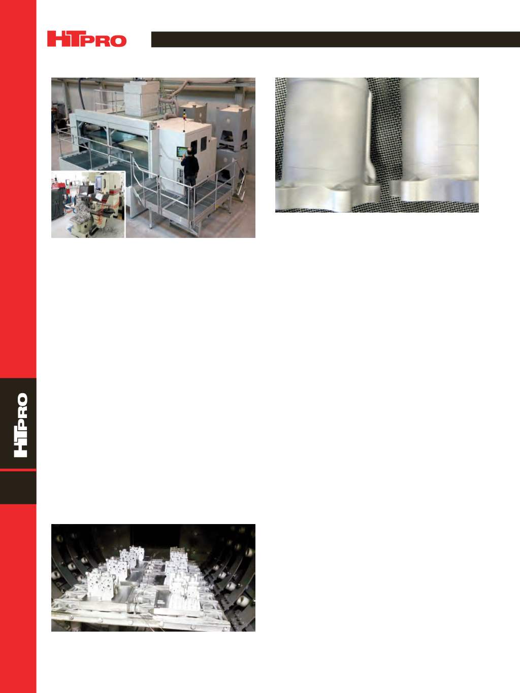
Fig. 4 —
These cracks indicate that parts were formed on a base
plate too thick relative to the printed features.